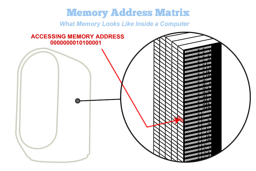
Image 5.1: The view of a memory loccation inside a computer
This diagram is a rendition of a single memory location inside a computer.
In this view, the processor is requesting the data stored in memory location 0000000010100001
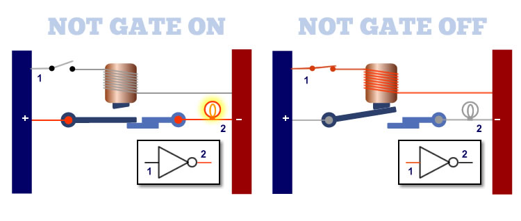
Image 5.2: Basic memory element logic, the NOT gate
In a NOT gate, when no current is applied to the input, the output is off.
A NOT gate will invert the input. When current is applied, the output is OFF. When no current is applied, the output is ON.
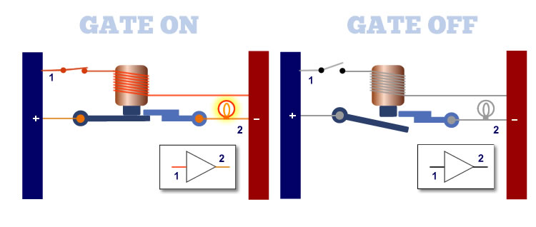
Image 5.3: A basic memory element, the logic buffer gate
The buffer gate passes the current throug for no net affect. If current is applied to the input, the output is ON.
The buffer gate is the opposite of the NOT gate. It merely passes current through to the output, for no net effect.
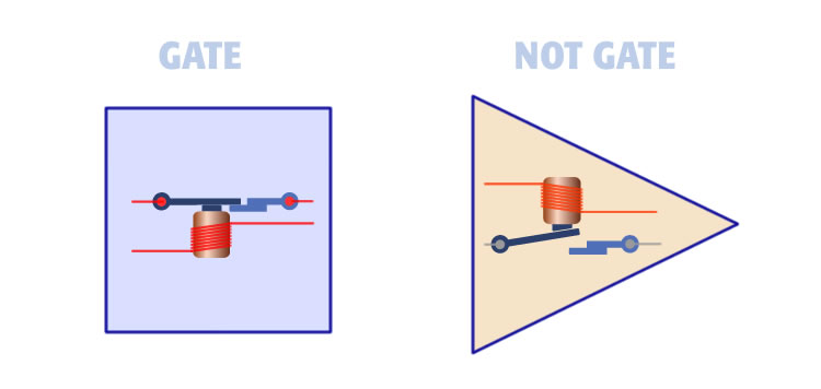
Image 5.4: Two basic logic elements of memory addressing
There are only two logic elements in a memory address matrix, the buffer gate and the NOT gate.
These two logic devices are expressed as a square (the buffer gate), and a triangle (the NOT gate).
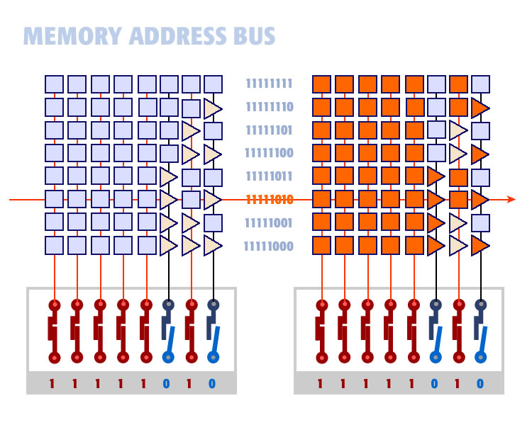
Image 5.5: Wiring an eight-bit memory address bus
This diagram shows the two memory logic gate arranged in a matrix so each memory location is unique.
This memory address bus shows how current can be applied to the address lines to access only one memory location.
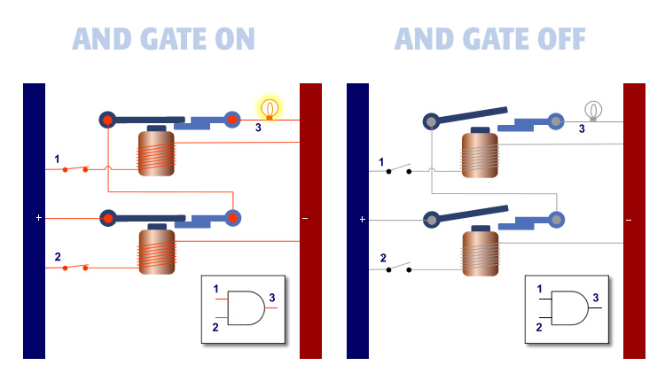
Image 5.6: An illustration of the basic AND gate and how it functions
The AND gate has two inputs. When both inputs are ON, the output is ON. When one or both inputs are OFF, the output is OFF.
The AND gate is intended to AND two inputs together. Only when both inputs are ON is the output ON.
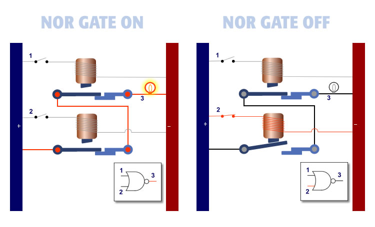
Image 5.7: The ohter basic memory logic element, the NOR gate and its functionality
The NOR gate is the opposite of the AND gate. When both inputs are OFF, the output is ON. In all other cases, the output is ON.
The NOR gate is fundamental in memory. In a NOR gate, both inputs must be OFF for the output to be ON.
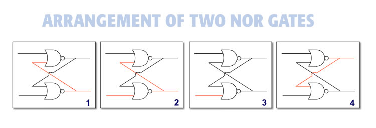
Image 5.8: The flipflop is a combination of NOR gates. The flipflop is the magic of memory.
A flipflop is a small device made by wiring two NOR gates together as shown. A flip-flop can be set permanently with a single burst of electricity.
This diagram shows how to set a flipflop into a permanent state. It shows how electricity applied in frame two will permanently set the flip-flop into its second state.
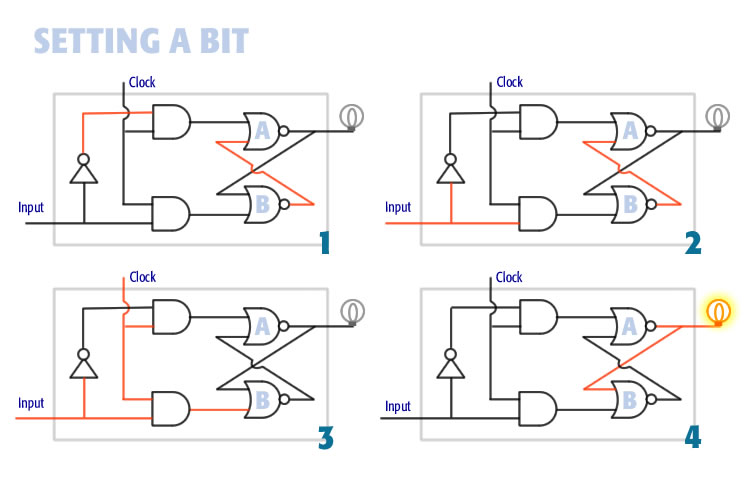
Image 5.9: A diagram of setting data the ON or OFF state into a binary digit (bit)
This diagram shows a single memory bit. In frame one, the bit is OFF. In frame 2, current is applied to the input. In frame 3, the clock goes high. In frame 4, the bit is permanently set to ON.
This diagram shows the main section of a single memory bit. This shows the sequence of events, taking the bit from the OFF state in frame 1, to ON in state 4. This memory bit relies on the flipflip. It is the basis for computer memory.
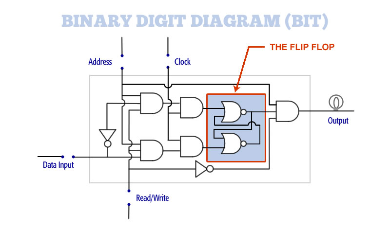
Image 5.10: A diagram showing a complete diagram of a binary digit
This is a diagram showing a complete memory bit, including data lines, address lines, clock, read-write, and output. At the heart of the memory bit is the flip-flop.
The memory bit is a simple logic device made up of a few logic elements. The bit can be permanently turned on and off by putting current on the various lines of the address bus.
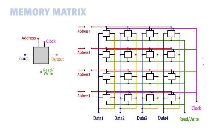
Image 5.11: A diagram showing a complete memory matrix with data, address, and read-write lines
This is a diagram of a memory bus within a computer. It shows 16 memory bits, arranged into a matrix, with the wires required to set and unset the bits.
Using this arrangemnt of bits and wires, the processor can move data into memory where it is retained. It can also get data out of memory, moving it to the processor. This is fully functional memory as shown.
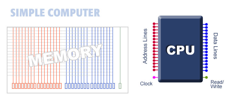
Image 5.12: An concept drawing of a central processing unit showing address and data lines
Artist rendition of a computer with 16 data lines, 16 address lines, a clock liine, and a read/write line
The only difference between this tiny 16-bit computer and the giant, powerful computers of today is size. The underlying concept is the same.
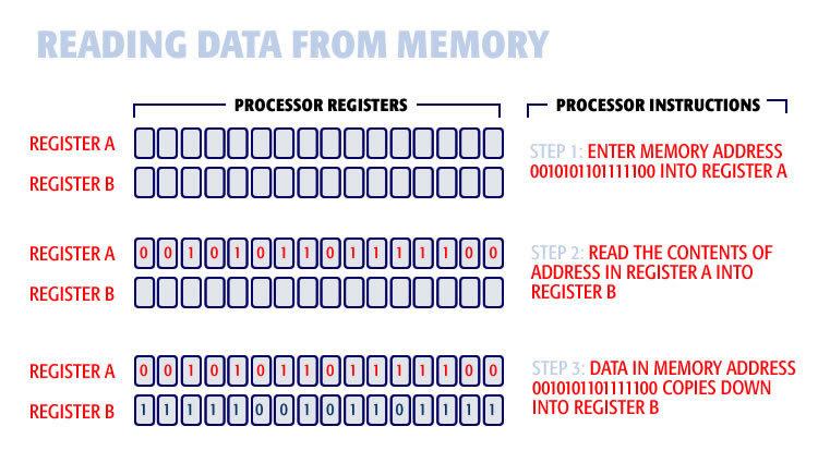
Image 5.13: How a computer processor reads data from memory
These are the memory registers inside the processor. To read data from memory, we load the memory address register A, issue the read instruction, and the data is brought down from memory into register B.
In this view, data is read from memory to a register inside the processor. This process is to load the local register, remote memory address, and issue the read command.
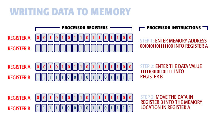
Image 5.14: How a computer process writes data to memory
Writing a data-word, from a register in the processor, to a remote memory location, is to load the data into one register, load the address into a second register, then issue the write command.
To write data to memory, we load the target memory address into register A, load the data to be saved into register B, and issue the write command. The data is loaded into that memory location.
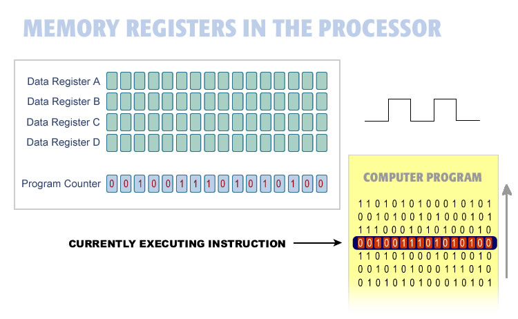
Image 5.15: A diagram showing how a computer thinks using programming
A computer program (shown in yellow) is a list of memory locations, data to be worked on, and processor instructions into a single program. The program runs by executing each line in succession.
Computer programs were originally a stack of punched cards, fed into the computer one at a time. Then someone realized that the program instructions could be loaded into memory and executed directly from there. No punch cards needed.
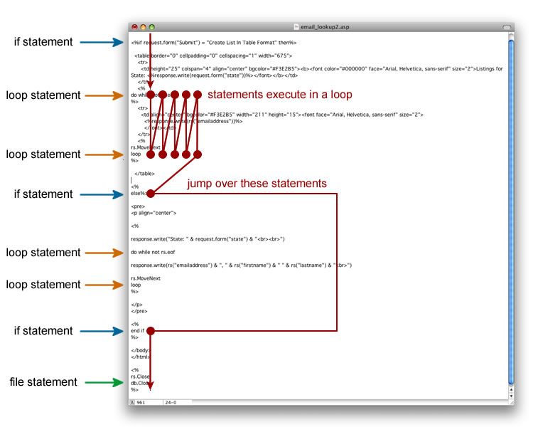
Image 5.16: A diagram showing the path of logic travel in a computer program
This is a diagram that follows the processor activity as it executes the program. The red line shows how the processor executes the program one line at a time.
The progress of the computer as it executes the instructions of a computer program look remarkably like conscious awareness operating within its environment.
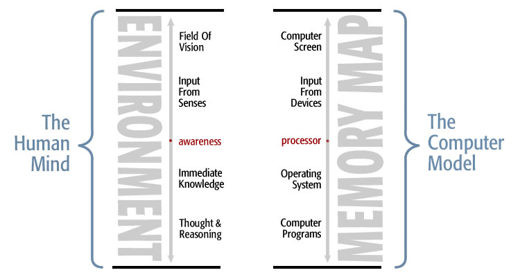
Image 5.17: An illustration comparing the human environment with a computer memory
This illustration compares the surrounding environment with the memory map of a computer. Both are rendered in memory.
This diagram is a side-by-side comparison of our surrounding environment and computer memory map. The two become strikingly similar when you realize that the environment, too, is resident in memory.
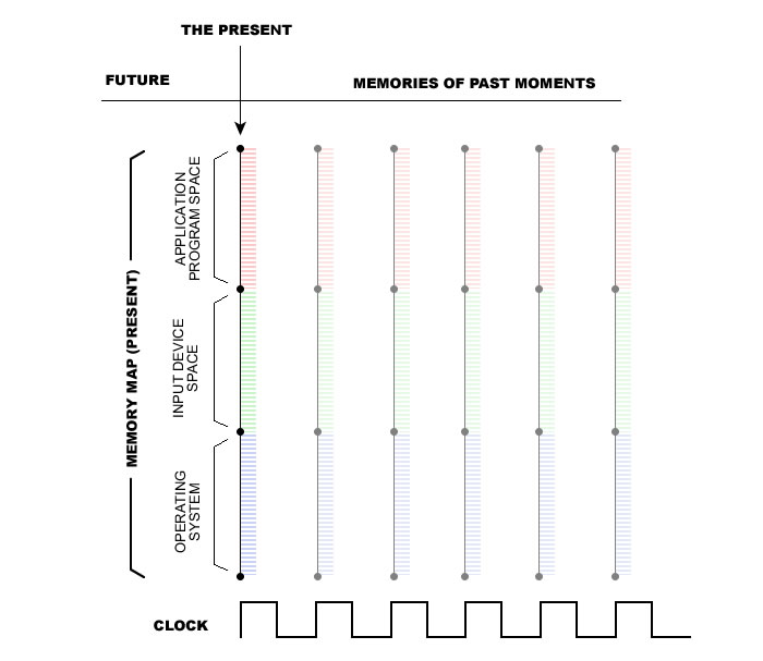
Image 5.18: A diagram of a computer memory space shown on a time line
This is a side-view of the memory map of a computer. Each vertical line represents all the memory in the computer at that point in time.
Each vertical line of this diagram represents the summed total of memory inside a computer. For each moment, this memory map includes the operating system, input space, and application programs - everything within memory at that time.
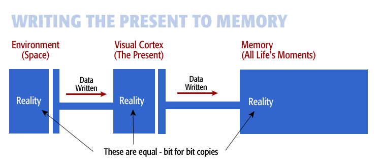
Image 5.19: A diagram showing how environmental data is written into memory thereby saving each moment
This diagram shows how the mind processes the environment into memory. Reality begins on the left, is built in the visual cortex, and is saved in long-term memory on the right.
Most people think of the outside world as outside of memory. This diagram shows the outside world on the left. Sensory input gets loaded into the visual cortex, where a model of the environment is built. Then this model gets passed into long-term memory, where it joins the other memories of moments of life.
Image 5.20: Memory capacity is equal to the number of data lines to the power of two
This equation shows the relationship between memory and the number of data-lines in a computer. If the computer has eight data lines, the total memory is 2 to the eighth power, or 256 memory locations.
In any computer, its memory size is determined by its number of data lines. Memory size is equal to two to the power of the number of data lines. This computer with 16 data lines will have a memory capacity of 65,000 memory locations.
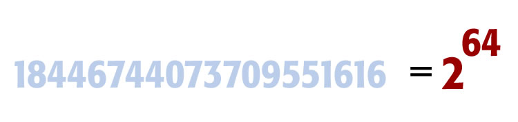
Image 5.21: Sixty four datalines will support a memory capacity of 17 billion gigabytes
This equations shows the number of memory locations in a computer with 64 data lines. The result is 64 squared, which is 18,446,744,073,709,551,616 memory locations.
Each data line added to a computer doubles its power. For example, 17 data lines will support twice the memory of 16 data lines. By the time you get to 64 data lines (computers now), you have a truly gigantic memory capacity.
Image 5.22: This equation expresses the relationship between aware (currently acted upon) memory versus unaware memory
In this diagram, we compare one data-word (processor register) to total memory in a 64-bit computer. The result is one over 17 billion.
Taking memory capacity a step further, a computer with 64 data lines will support up to 17 billion memory locations. This is the ratio between memory in the processor and memory at large, as shown on the right.
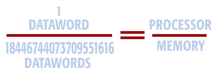
Image 5.23: An equation of a dataword over memory equals awareness over memory
In this equation we make a direct comparison between a data-word over total memory, and conscious awareness over memory (environment).
This equation draws a comparison between the memory in the processor, versus total memory. This ratio is similar to conscious awareness in the environment and the environment at large. Conscious awareness operates as a (0D) location, within a (3D) environment, resident in memory.
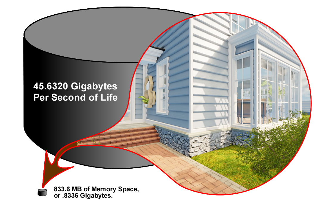
Image 5.24: This diagram shows the physical memory requirements for storing a three dimensional reality
The diagram shows the memory required to store a fully developed environment of a house. The implication is that this 3D model memory requirement is about the same size as storing a moment of reality. The result is 45 gigabytes. A 64-bit computer can store 17 billion gigabytes.
It would appear as though the human memory needs would out-strip computer memory in terms of capacity. This illustration compares the memory required to hold a complex 3D model versus the total memory capacity of a 64-bit computer. It may be that a computer could hold all moments throughout life in memory after all.
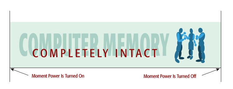
Image 5.25: A diagram showing a lifetime stored completely intact into memory
This diagram shows that total memory begins at the moment life begins, retains everything during life, the ends the moment life turns off. The results is a four-dimensional (4D) time-space continuum.
It is commonly thought that something special needs to happen for afterlife to become a reality. It does not. This illustration shows that a computer memory time-space continuum exists within all of us, containing every detail from every moment throughout life. So nothing special needs to take place because it is already there at all times. The afterlife system works, and no warning is required. It is revealed at the last moment.